
Abstraction
For a small company, it is quite common to have two of four servers, two switches which often supports Multi-chassis EtherChannel and a low-end storage system. It is quite vital for such companies to utilize their infrastructure fully and thus all available technologies and this article describe one aspect of how to do this with ONTAP systems. Usually, there is no need to dig too deep into LACP technology but to those who want to, welcome to this post.
It is essential not just to tune and optimize one part of your infrastructure but the whole stack to achieve the best performance. For instance, if you optimize only the network, the storage system might become a bottleneck in your environment and vice versa.
Majority of modern servers have on-board 1 Gbps or even 10 Gbps Ethernet ports.
In some of the old ONTAP storage systems like FAS255X and more modern FAS26XX have 10Gbps onboard ports. In this article, I am going to focus on an example with a FAS26XX system with 4x 10Gbps ports on each node, and two servers with 2x 10Gbps ports and a Cisco switch with 10Gbps ports and support for Multi-chassis EtherChannel. However, this article would apply to any small configuration.
Scope
So, we would like to be able to fully utilize network bandwidth in storage system and servers and prevent any bottlenecks. One way to do this is to use iSCSI or FCP protocols which have built-in load balancing and redundancy thus in this article we going to overview protocols which do not have such an ability, like CIFS and NFS. Why would users be interested in those NAS protocols which don’t have built-in load balancing and redundancy? Because NAS protocols have file granularity and file visibility from ONTAP perspective and in combination in many cases give more agility then SAN protocols while network “features” of NAS protocols could easily enough be compensated with functionality of network switches build-in nearly in any switch. Of course, technologies not magically work, and, in each approach, there are some nuances and considerations.
In many cases, users would like to use both SAN and NAS on top of a single pair of Ethernet ports with ONTAP systems, and for this reason, the first thing you should consider is NAS protocols with load balancing and redundancy and only then adapt SAN connection to it. NAS protocols with SAN on top of Ethernet ports often case for customers with smaller ONTAP systems where the number of Ethernet ports is limited.
Also, in this article, I am going to avoid technologies like VVols over NAS, pNFS, dNFS and SMB multichannel. I would like to write about VVol in another dedicated article while it is not related to NAS or SAN protocols directly but can be part of the solution which provides on one hand file granularity, and on another hand can use NFS or iSCSI, where iSCSI could natively load-balance traffic across all available network paths. pNFS unfortunately currently supported only with RedHat/CentOS systems for enterprise environments, not widespread and does not provide native load balancing because NFS Trunking currently in the draft while SMB multichannel currently not supported with ONTAP 9.3 itself.
In this situation, we have few configurations left.
- One is to use NAS protocols solely with Ethernet port aggregation
- Another one is to use NAS protocols with Ethernet port aggregation and SAN on top of aggregated ports, which could be divided into two subgroups:
- Where you are using iSCSI as SAN protocol
- Where you are using FCoE as SAN protocol
- Native FC protocol require dedicated ports and could not work over Ethernet ports
Even though FCoE on top of aggregated Ethernet ports with NAS is possible networking configuration with ONTAP system, I am not going discuss it in this article because FCoE is supported only with expensive converged network switches like Nexus 5000 or 7000 thus not scope of interest of small companies. Though NAS with right configuration can provide entirely compatible performance, load balancing, and redundancy to FC & FCoE with ONTAP systems, so there is no reason to pay more.
NAS protocols with Ethernet port aggregation
Both variants: NAS protocols with Ethernet port aggregation and NAS protocols with Ethernet port aggregation with iSCSI on top of aggregated ports have quite a similar network configuration and topology. Also, this is the configuration Its going to describe in this article.
Theoretical part
Unfortunately, Ethernet load balancing works not sophisticated as in SAN protocols in a quite simple way. I personally even would call it load-distribution instead of load-balancing. In fact, Ethernet not paying attention to “balancing” part and not actually trying to distribute workload across links evenly, instead it just distributing workload hoping that there would be plenty of network nodes generating read and write threads and only because of Probability theory workload would be more or less evenly distributed. The fewer nodes in the network, the fewer network threads, the less probability that each network link is going to be equally loaded across network links and vice versa.
The most straightforward algorithm for Ethernet load balancing is sequentially picking one of the network links for each new thread, one by one. Another algorithm uses hash sum from the network address of sender and recipient to peek one network link in the aggregate. Network address could be IP address or MAC address or something else. Moreover, this small nuance plays a role in this article and your infrastructure. Because in case if a source and a destination address hash sum going to be same, therefore the algorithm going to use the same link in the aggregate. In other words, it is essential to understand how load balancing algorithm works to make sure that combinations of network addresses would be such that you not only get redundant network connectivity but also to ensure you are going to utilize all network links. Especially it becomes vital for small companies with few participants in their network.
It is quite often that 4 servers could not fully utilize 10Gbps links, but during peak utilization, it is essential to distribute network threads between links evenly.
Typical network topology and configuration for small companies
In my example, we have 2 servers, 2 switches, and one storage system with two storage nodes running ONTAP 8.3 or higher with the following configuration, and also keep in mind:
- From a storage node, two links go one to the first switch, another link to the second switch
- Switches configured with technologies like vPC (or similar) or switches are stacked
- Switches configured with Multi-chassis EtherChannel/PortChannel technology, so two links from the server connected to two switches aggregated in a single EtherChannel/PortChannel. Links from a storage node connected to two switches aggregated in a single EtherChannel/PortChannel.
- LACP with IP load balancing configured over EtherChannel
- 10Gbps switch ports connected to servers and storage set with Flow control = disable
- Storage system ports and server ports set with Flow control = disable (none)
- 4 links on first storage node aggregated in a single EtherChannel (ifgroup) with configured LACP (multimode_lacp), same with second storage node. In total two ifgroup, one on each storage node
- Same NFS VLAN created on top of each ifgroup, one on the first storage node, second on the second storage node
- On each of two NFS VLAN created 2x IP addresses, 4 in total on two storage nodes
- Storage nodes each have at least one data aggregate created out of an equal number of disks, for example, each aggregate could be:
- 9 data + 2 parity disks and 1 hot spare
- 20 data + 3 parity disks and 1 hot spare
- Volumes on top of data aggregates configured as:
- Either one FlexGroup spanned on all aggregates
- Alternatively, 2 volumes on each storage node – 4 total, which is minimal and sufficient
- Each server has two 10Gbps ports, one port connected to one switch, the second port to the second switch
- On each server 2x 10Gbps links aggregated in EtherChannel with LACP
- Jumbo frame enabled on all components: storage system ports, server ports, and switch ports
- Each volume mounted on each server as a file share, so each server is going to be able to use all 4 volumes.
Minimum number of volumes for even traffic distribution is pretty much determined by the biggest number of links from either a storage system or a server; in this example, we have 4 ports on each storage nodes, which means we need 4 volumes total. In case if you have only 2 network links from each server and two from a storage system node, I will still suggest keeping at least 4 volumes which are useful not only for network load balancing but also for storage node CPU load balancing. In case of FlexGroup, it is enough to have only one such a group but keep in mind that it is currently not optimized for high metadata workloads like virtual machines and databases.
One IP addresses for each storage node with two or four links on each node in configurations with two or more hosts each with two or four links and with one IP addresses for each host, almost always enough to provide even network distribution. However, with one IP address for each storage node and one IP address for each host, even distribution could be achieved in perfect scenarios where each host is going to access each IP address evenly what on practice hard to achievable, quite hard to predict, and it could change with time. So, to increase the probability of more even network load distribution, we need to divide traffic in more threads, and the only way to do this with LACP is to increase the number of IP addresses. Thus, for small configurations with two of four hosts and two storage nodes each with 2x IP addresses instead of one could increase the probability of more even network traffic distribution across all network links.
Unfortunately, conventional NAS protocols do not allow hosts to recognize a file share mounted with different IP addresses as a single entity. So, for example, if we are will mount an NFS file share to VMware ESXi with two different IP addresses, the hypervisor will see it as two different Datastores. In case you are interested in network link re-balancing, a VM needs to be migrated on a Datastore with different IP but to move that VM, storage vMotion going to be involved even though it is the same network file share (volume).
Network Design
Here is recommended and well-known network design often used with NAS protocols.
|
(1)
|
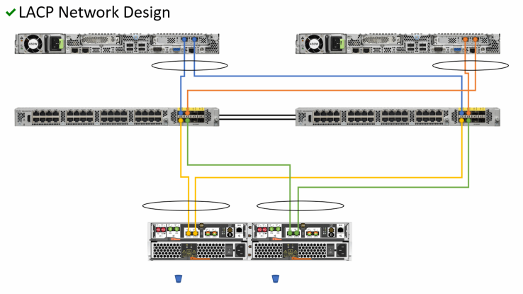
However, merely cabling and configuring switches with LACP doesn’t guarantee you that network traffic is going to be balanced across all the links in the most efficient way, well, it depends, and even if it is this can change after a while. To ensure we get maximum from both network and storage system, we need to tune them a bit, to do so we need to understand how LACP and storage system works. For more network designs, including bad designs, see slides here.
|
(2)
|

LACP protocol & algorithm
In ONTAP world nodes in a storage system for NAS protocols work it disadvantages as they separated from each other, so you can percept them as separated servers this architecture called share-nothing. The only difference is if one storage node die second will take its disks, workloads and copy IP so hosts going to continue to work with its data as nothing happens, this called takeover in a High Availability pare; also with ONTAP you can move IP and Volumes online between storage nodes, but let’s not focus on this. Since we remember that storage nodes as independent servers LACP protocol could aggregate few Ethernet ports only within a single node, so it does not allow you to aggregate ports from multiple storage nodes. While with Switches we can configure Multi-Chassis Ether Channel, so LACP protocol is done ports from few switches.
Now LACP algorithm selects a link only for the next hop, one step at a time so the full path from sender to a recipient not established nor handled by the initiator as it is done in SAN. Communication between same two network nodes could be sent through one path while response could come back through another path. LACP algorithm uses the hash sum of a source and destination addresses to select the path. The only way to ensure your traffic goes by expected paths with LACP protocol is to enable load balancing by IP, or MAC addresses hash sum and then calculate hash sum result or test it on your equipment. With right combination of source and destination address, you can ensure LACP algorithm going to select your preferred path.
LACP algorithm could be realized in different ways on a server, switch, and storage system, that’s why traffic from the server to storage and from storage to the server could go through different paths.
There are few essential addition circumstances which going to influence on your storage system data partitioning and on source & destination IP address selection. There are applications which can share volumes like VMware vSphere where each ESXi host can work with multiple volumes; and configurations where volumes not shared by your applications.
One volume & one IP per node
Since we have two ONTAP nodes with share-nothing, and we want to utilize storage systems fully, we need to create volumes on each node and thus at least one IP on each node on top of aggregated Ethernet interface. Each aggregated interface consists of two Ethernet ports. In the next network designs some of the objects thin not displayed (such as network links and server) to focus on some of the aspects, note that all the next network designs are based on the very first image “LACP network design.”
|
(3A)
|

Let’s see the same example but from the storage perspective. Let me remind you that in the next network designs some of the objects were not displayed (such as network links and server) to focus on some of the aspects, note that all the next network designs are based on the very first image “LACP network design.”
|
(3B)
|

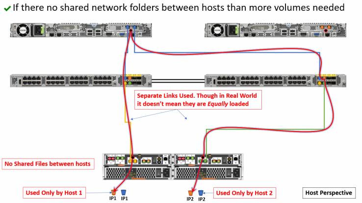
Two volumes & one IP per node
However, some of the configurations do not share volumes between applications running on your servers. So, to utilize network all the links we need to create on each storage node in two volumes: one used only by host1, second used only by host2. Volumes and connections to the second node not displayed to make image simple, in reality, they are existing and are symmetrical to the first storage node.
|
(4A)
|

Let’s see the same configuration but from the storage perspective. As in previous images symmetrical part of connections are not displayed to simplify image: in this case symmetrical connections to blue buckets on each storage node not displayed but in real configuration exists.
|
(4B)
|
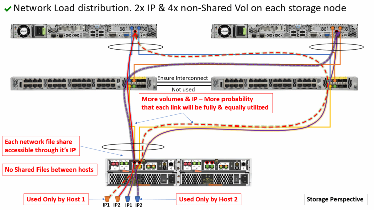
Two volumes & two IPs per node
Now if we are going to increase the number of IP, we can mount each volume over two different IP addresses. In such a scenario each mount is going to be percepted by hosts as two separate volume even though it is physically the same volume with same data set. In this situation often makes sense to also increase the number of volumes so that each volume going to be mounted with its own IP. Thus, we are going to achieve more even network load distribution across all the links, either for shared or non-shared application configuration.
|
(5A)
|

In non-Shared volume configuration each volume used by only one host. Designs 5A & 5B are quite similar and differ one from another only by how the volumes are mounted on hosts.
|
(5B)
|

Four volumes & two IPs per node
Now if we are going to add more volumes and IP addresses to our configuration where we have two applications which not share volumes and could achieve even better network load balancing across links with a right combination of network share mounts. The same design could be used with an application which shares volumes and similar to the design on image 5.
|
(6)
|
For more network designs, including bad designs, see slides here.
Which design is better?
Whether your applications using shared volumes or not, I would recommend:
- Design #3 for environments where you have multiple independent applications, so with multiple apps you are going to have in total at least 4 or more volumes on each storage node.
- Alternatively, Design #6 if you are running only one application like VMware vSphere and not planning to add new applications and volumes. Use 4 volumes per node minimum whether you have shared or non-shared volumes.
How to ensure network traffic goes by expected path?
This is more complex and geeky part. In the real world, you can run in a situation where your switch can decide to put your traffic through additional hop or hash sum from your source, and destination addresses pare of two or more pares could overlap. To ensure your network traffic goes by the expected path you need to calculate the hash sum. Usually, in big enough environments where you have many volumes, file shares, and IP addresses, you do not care about this because more IP you have more probability that your traffic will distribute the workload over your links troubleshooting because of the Probability theory. However, if you care and you have a small environment, you can brute force passwords IPs for your server and storage.
Configuring ONTAP
Create data aggregate
cluster1::*> aggr create -aggregate aggr -diskcount 13
Create SVM
cluster1::*> vserver create -vserver vsm_NAS -subtype default -rootvolume svm_root -rootvolume-security-style mixed -language C.UTF-8 -snapshot-policy default -is-repository false -foreground true -aggregate aggr -ipspace Default
Create aggregated ports
cluster1::*> ifgrp create -node cluster1-01 -ifgrp a0a
cluster1::*> ifgrp create -node cluster1-02 -ifgrp a0a
Create VLANs for each protocol-mtu
cluster1::*> vlan create -node * -vlan-name a0a-100
I would recommend creating dedicated broadcast domains for each combination protocol-mtu. For example:
- Client-SMB-1500
- Server-SMB-9000
- NFS-9000
- iSCSI-9000
cluster1::*> broadcast-domain create -broadcast-domain Client-SMB-1500 -mtu 1500 -ipspace Default -ports cluster1-01:a0a-100,cluster1-02:a0a-100
Create interfaces with IP addresses
cluster1::*> vserver create -vserver vsm_NAS -subtype default -rootvolume svm_root -rootvolume-security-style mixed -language C.UTF-8 -snapshot-policy default -is-repository false -foreground true -aggregate aggr -ipspace Default
If you haven’t created dedicated broadcast domains, then configure fail-over policies for each protocol and assign it to LIF interface.
cluster1::*> network interface failover-groups create -vserver vsm_NAS -failover-group FG_NFS-9000 -targets cluster1-01:a0a-100, cluster1-02:a0a-100
cluster1::*> network interface modify -vserver vsm_NAS -lif nfs01_1 -failover-group FG_NFS-9000
Configuring Switches
This topic is the place where 90% of human error done. People often forget to add word “active” or add it to right place etc.
Example of Switch configuration
Cisco Catalyst 3850 in a stack with 1Gb/s ports
Note “mode active” means “multimode_lacp” in ONTAP, so each interface must have next configuration: “channel-group X mode active,” not Port-channel. Note configuration “flowcontrol receive on” depends on port speed, so if storage sends flow control, then “other side” must receive it. Note it is recommended to use RSTP, in our case with VLANs it is Rapid‐PVST+ and configure switch ports connected to storage and servers with spanning-tree portfast.
system mtu 9198
!
spanning-tree mode rapid-pvst
!
interface Port-channel1
 description N1A-1G-e0a-e0b
 switchport trunk native vlan 1
 switchport trunk allowed vlan 53
 switchport mode trunk
 flowcontrol receive on
 spanning-tree guard loop
!
interface Port-channel2
 description N1B-1G-e0a-e0b
 switchport trunk native vlan 1
 switchport trunk allowed vlan 53
 switchport mode trunk
 flowcontrol receive on
 spanning-tree guard loop
!
interface GigabitEthernet1/0/1
 description NetApp-A-e0a
 switchport trunk native vlan 1
 switchport trunk allowed vlan 53
 switchport mode trunk
 flowcontrol receive on
 cdp enable
 channel-group 1 mode active
 spanning-tree guard loop
 spanning-tree portfast trunk feature
!
interface GigabitEthernet2/0/1
 description NetApp-A-e0b
 switchport trunk native vlan 1
 switchport trunk allowed vlan 53
 switchport mode trunk
 flowcontrol receive on
 cdp enable
 channel-group 1 mode active
 spanning-tree guard loop
 spanning-tree portfast trunk feature
!
interface GigabitEthernet1/0/2
 description NetApp-B-e0a
 switchport trunk native vlan 1
 switchport trunk allowed vlan 53
 switchport mode trunk
 flowcontrol receive on
 cdp enable
 channel-group 2 mode active
 spanning-tree guard loop
 spanning-tree portfast trunk feature
!
interface GigabitEthernet2/0/2
 description NetApp-B-e0b
 switchport trunk native vlan 1
 switchport trunk allowed vlan 53
 switchport mode trunk
 flowcontrol receive on
 cdp enable
 channel-group 2 mode active
 spanning-tree guard loop
 spanning-tree portfast trunk feature
Cisco Catalyst 6509 in a stack with 1Gb/s ports
Note “mode active” means “multimode_lacp” in ONTAP, so each interface must have next configuration: “channel-group X mode active,” not Port-channel. Note configuration “flowcontrol receive on” depends on port speed, so if storage sends flow control, then “other side” must receive it. Note it is recommended to use RSTP, in our case with VLANs it is Rapid‐PVST+ and configure switch ports connected to storage and servers with spanning-tree portfast.
system mtu 9198
!
spanning-tree mode rapid-pvst
!
interface Port-channel11
 description NetApp-A-e0a-e0b
 switchport trunk native vlan 1
 switchport trunk allowed vlan 53
 switchport mode trunk
 flowcontrol receive on
 spanning-tree guard loop
 spanning-tree portfast trunk feature
!
interface Port-channel12
 description NetApp-B-e0a-e0b
 switchport trunk native vlan 1
 switchport trunk allowed vlan 53
 switchport mode trunk
 flowcontrol receive on
 spanning-tree guard loop
 spanning-tree portfast trunk feature
!
interface GigabitEthernet1/0/1
 description NetApp-A-e0a
 switchport trunk encapsulation dot1q
 switchport trunk native vlan 1
 switchport trunk allowed vlan 53
 switchport mode trunk
 flowcontrol receive on
 cdp enable
 channel-group 11 mode active
 spanning-tree guard loop
 spanning-tree portfast trunk feature
!
interface GigabitEthernet2/0/1
 description NetApp-A-e0b
 switchport trunk encapsulation dot1q
 switchport trunk native vlan 1
 switchport trunk allowed vlan 53
 switchport mode trunk
 flowcontrol receive on
 cdp enable
 channel-group 11 mode active
 spanning-tree guard loop
 spanning-tree portfast trunk feature
!
interface GigabitEthernet1/0/2
 description NetApp-B-e0a
 switchport trunk encapsulation dot1q
 switchport trunk native vlan 1
 switchport trunk allowed vlan 53
 switchport mode trunk
 flowcontrol receive on
 cdp enable
 channel-group 12 mode active
 spanning-tree guard loop
 spanning-tree portfast trunk feature
!
interface GigabitEthernet2/0/2
 description NetApp-B-e0b
 switchport trunk encapsulation dot1q
 switchport trunk native vlan 1
 switchport trunk allowed vlan 53
 switchport mode trunk
 flowcontrol receive on
 cdp enable
 channel-group 12 mode active
 spanning-tree guard loop
 spanning-tree portfast trunk feature
Cisco Small Business SG500 in a stack with 10Gb/s ports
Note “mode active” means “multimode_lacp” in ONTAP, so each interface must have next configuration: “channel-group X mode active,” not Port-channel. Note configuration “flowcontrol off” depends on port speed, so if storage not using flow control (flowcontrol none), then on “other side” flowcontrol must also be disabled. Note it is recommended to use RSTP and configure switch ports connected to storage and servers with spanning-tree portfast.
interface Port-channel1 description N1A-10G-e1a-e1b
 spanning-tree ddportfast
 switchport trunk allowed
 vlan add 53
 macro description host
 !next command is internal.
 macro auto smartport dynamic_type host
 flowcontrol off
!
interface Port-channel2
 description N1B-10G-e1a-e1b
 spanning-tree ddportfast
 switchport trunk allowed
 vlan add 53
 macro description host
 !next command is internal.
macro auto smartport
 dynamic_type host
 flowcontrol off
!
port jumbo-frame
!
interface tengigabitEthernet1/1/1
 description NetApp-A-e1a
 channel-group 1 mode active
 flowcontrol off
!
interface tengigabitEthernet2/1/1
 description NetApp-A-e1b
 channel-group 1 mode active
 flowcontrol off
!
interface tengigabitEthernet1/1/2
 description NetApp-B-e1a
 channel-group 2 mode active
 flowcontrol off
!
interface tengigabitEthernet2/1/2
 description NetApp-B-e1b
 channel-group 2 mode active
 flowcontrol off
HP 6120XG switch in blade chassis HP c7000 and 10Gb/s ports
Note “trunk 17-18 Trk1 LACP” means “multimode_lacp” in ONTAP. Note configuration “flowcontrol off” not present in here which means it set to “auto” by default so if a network node connected to the switch going to have disabled Flow control, then the switch not going to use it also. Flow control depends on port speed, so if storage not using flow control (flowcontrol none), then on “other side” flowcontrol must also be disabled. Note it is recommended to use RSTP and configure switch ports connected to storage and servers with spanning-tree portfast.
# HP 6120XG from HP c7000 10Gb/s
trunk 11-12 Trk10 LACP
trunk 18-19 Trk20 LACP
vlan 201
   name "N1AB-10G-e1a-e1b-201"
   ip address 192.168.201.222 255.255.255.0
   tagged Trk1-Trk2
   jumbo
   exit
vlan 202
   name "N1AB-10G-e1a-e1b-202"
   tagged Trk1-Trk2
   no ip address
   jumbo
   exit
spanning-tree force-version rstp-operation
Switch troubleshooting
Let’s take a look at the switch output
                               Rx                           TxPort
      Mode    | ------------------------- | -------------------------
              | Kbits/sec  Pkts/sec  Util | Kbits/sec Pkts/sec  Util
------- --------- + ---------- --------- ---- + ---------- ---------- ---
Storage
1/11-Trk21 1000FDx| 5000      0         00.50 | 23088     7591      02.30
1/12-Trk20 1000FDx| 814232    12453     81.42 | 19576     3979      01.95
2/11-Trk21 1000FDx| 810920    12276     81.09 | 20528     3938      02.05
2/12-Trk20 1000FDx| 811232    12280     81.12 | 23024     7596      02.30
Server
1/17-Trk11 1000FDx| 23000     7594      02.30 | 810848    12275     81.08
1/18-Trk10 1000FDx| 23072     7592      02.30 | 410320    6242      41.03
2/17-Trk11 1000FDx| 19504     3982      01.95 | 408952    6235      40.89
2/18-Trk10 1000FDx| 20544     3940      02.05 | 811184    12281     81.11
We can clearly see that one of the links is not utilized. Why does it happen? Because sometimes the algorithm which calculates the hash sum of a pair of source and destination addresses generates the same value for two (or more) pairs of source and destination addresses.
SuperFastHash in ONTAP
Instead of ordinary algorithm widely used by hosts and switches ((source_address XOR destination_address) % number_of_links), ONTAP starting with 7.3.2 using the algorithm called SuperFastHash which gives more dynamic, more balanced load distribution for a big number of clients, so each TCP session associated with only one physical port.
The ONTAL-LACP algorithm is available at GitHub under BSD license. Though I did my best to make it precise and fully functional, I do not give any guarantees so that you can use it AS IS.
You can use the online compiler. You need to find storage IP with the biggest number in “SUM Total Used” column.
This compiler built-in you result what physical port is going to be picked up depending on Troubleshootingsource and destination address.
Let’s create a table for network Design #4A using the output from our simple code. Here is output example
With following variables:
    st_ports = 2;
    srv_ports = 2;
    subnet = 53;
    src_start = 21;
    src_end = 22;
    dst_start = 30;
    dst_end = 50;
Output:
       ¦NTAP       %  ¦NTAP       %  ¦Srv        %  ¦ SUM¦
       ¦OUT      |Path¦IN       |Path¦IN&O     |Path¦Totl¦
   IP  ¦  21|  22|Used¦  21|  22|Used¦  21|  22|Used¦Used¦
 53.30 ¦   1|   0|  75|   1|   0|  75|   1|   0| 100|  83|
 53.31 ¦   1|   1|  37|   0|   1|  62|   0|   1| 100|  66|
 53.32 ¦   0|   1|  75|   1|   0|  75|   1|   0| 100|  83|
 53.33 ¦   0|   1|  75|   0|   1|  75|   0|   1| 100|  83|
 53.34 ¦   0|   1|  75|   1|   0|  75|   1|   0| 100|  83|
 53.35 ¦   0|   0|  37|   0|   1|  62|   0|   1| 100|  66|
 53.36 ¦   1|   0|  75|   1|   0|  75|   1|   0| 100|  83|
 53.37 ¦   1|   0|  75|   0|   1|  75|   0|   1| 100|  83|
 53.38 ¦   0|   0|  37|   1|   0|  62|   1|   0| 100|  66|
 53.39 ¦   0|   1|  75|   0|   1|  75|   0|   1| 100|  83|
 53.40 ¦   1|   0|  75|   1|   0|  75|   1|   0| 100|  83|
 53.41 ¦   1|   0|  75|   0|   1|  75|   0|   1| 100|  83|
 53.42 ¦   1|   0|  75|   1|   0|  75|   1|   0| 100|  83|
 53.43 ¦   0|   1|  75|   0|   1|  75|   0|   1| 100|  83|
 53.44 ¦   0|   0|  37|   1|   0|  62|   1|   0| 100|  66|
 53.45 ¦   0|   1|  75|   0|   1|  75|   0|   1| 100|  83|
 53.46 ¦   1|   1|  37|   1|   0|  62|   1|   0| 100|  66|
 53.47 ¦   0|   0|  37|   0|   1|  62|   0|   1| 100|  66|
 53.48 ¦   1|   0|  75|   1|   0|  75|   1|   0| 100|  83|
 53.49 ¦   1|   0|  75|   0|   1|  75|   0|   1| 100|  83|
 53.50 ¦   1|   0|  75|   1|   0|  75|   1|   0| 100|  83|
So, you can use IP addresses XXX.XXX.53.30 for your first storage node and XXX.XXX.53.32 for your second storage node at Design #4.
Disadvantages in conventional NAS protocols with Ethernet LACP
Each technology doesn’t work magically and have its own advantages and disadvantages; it is essential to know and understand them.
- You cannot aggregate two network file shares into one logical space as with LUNs
- If a storage vendor gives you an aggregation of few volumes for NAS on a storage system, data distribution often is done with the granularity of file-level:
- Load distribution based on Files depends on their size and could be not equal
- Load distribution not suitable for high metadata or high re-write workloads.
- With Ethernet LACP Full path between pears not established nor controlled by initiators
- Each Next Step is chosen individually: Path towards and backward could be different
- LACP does not allow you to aggregate ports from multiple storage nodes.
- No SAN ALUA-like multipathing:
- LACP allows to aggregate only ports in a single server or a single storage node
- Multi-Chassis ether Chenal require special switches, though it available nearly in any switches
- Only a few switches could be in an LACP stack. Entry-level stacked switches could be unstable which limits scalability.
- If a storage vendor gives you an aggregation of few volumes for NAS on a storage system, data distribution often is done with the granularity of file-level:
Because of these disadvantages, conventional NAS protocols with LACP usually could not achieve full network link utilization and must be tuned manually to do so. Though LACP not ideal
- it was available for years nearly in any Ethernet switch
- it is the only best solution currently we have with conventional NAS protocols
- it is definitely better than conventional NAS without it.
Advantages of NAS protocols over Ethernet
LACP has it’s disadvantages and adds them to conventional NAS protocols which don’t have built-in multipathing and load-balancing, though NAS protocols still more attractive with ONTAP because:
NAS:
- NAS have data visibility in Snapshots
- More space efficient than SAN in many ways
- File-granular access in snapshots
- Individual file copy, no FlexClone or SnapRestore licenses needed
- Individual file restores or clone (FlexClone or SnapRestore licenses required)
- Backup data mining for cataloging
- Accessed directly on storage, no host mounting needed.
Ethernet & LACP:
- Ethernet switches are cheaper then InfiniBand & FC
- LACP & Multi-Chassis Ether Channel available nearly with any switch
- 1, 10, 25, 40, 50, 100 Gb/s available as single pipe
- Multi-purposes, Multi-protocol, Multi-tenancy with VLANs
- Cheaper Multi-site: VPN, VXLAN
- Routing on top of Ethernet available for FCoE, iSCSI, NFS, CIFS.
Looking to the future
Though NAS protocols have their disadvantages because they do not have built-in multipathing and load-balancing they rely on LACP, they evolve and bit by bit copying abilities from other protocols.
For example, SMB v3 protocol with Contiguous Availability feature can survive online IP movement between ports and nodes without disruption which is available in ONTAP, thus can be used with MS SQL & Hyper-V. Also, SMB v3 protocol supports multichannel which provides built-in link aggregation and load balancing without relying on LACP, currently not supported in ONTAP.
NFS from the beginning was not session protocol so with IP move to another storage node application survives. Further NFS evolves and in version 4.1 get a feature called pNFS which provide the ability to automatically and in a transparent way to switch between nodes and ports in case data been moved to follow the data similarly to SAN ALUA, which is also available in ONTAP. Version 4.1 of NFS also include session trunking feature, similarly to SMB v3 multichannel feature it will allow to aggregate links without relying on LACP, currently not supported in ONTAP. NetApp drives NFS v4 protocol with IETF, SNIA and open-source community to accept it as soon as possible.
Conclusion
Though NAS protocols have disadvantages, mainly because of underlying Ethernet & more precise LACP, it is possible to tune LACP to mostly efficient utilize your network and storage. With big environments usually, no need for tuning but for small environments load balancing might become a bottleneck especially if you are using 1 Gb/s ports. Though it is rare to fully utilize network performance of 10Gb/s ports in small environments, tuning is better to do at the very beginning then later on a production environment. NAS protocols are file granular, and since storage system run underlying FS, it can work with files and provide more abilities for thin provisioning, cloning, self-service operations and backup in many ways agiler then SAN. NAS protocols are evolving and absorb abilities from other protocols, to be particular, SAN protocols like FC & iSCSI, to entirely diminish their disadvantages and already provide additional capabilities to environments which can use new versions of SMB and NFS.
Troubleshooting
90% of all the problems is network configuration on the switch side, 10% other on the host side. Human error
